
English


Views: 289 Author: Dapeng Aluminum Publish Time: 2026-10-02 Origin: Site


Content Menu
● What Is an Extruded Aluminum Channel?
● Which Aluminum Channel Shape Fits Your Application?
>> U-Channels: Edge Protection and Simple Guides
>> C-Channels: Tracks and Captured Components
>> J-Channels: Clean Panel Edges
>> Z-Channels: Offset Mounting
>> Hat Channels: Raised Support Lines
>> T- and H-Profiles: Dividing and Joining
● How to Specify Dimensions That Actually Fit
>> Separate Critical Dimensions From General Dimensions
>> Plan for Finishing and Assembly
● Choose the Alloy and Temper for the Job
● Match the Finish to the Service Environment
● Example: Specifying a Solar Equipment Guide Channel
● A Buyer's Checklist for Custom Channels
● Work With a Manufacturer on the Complete Profile
>> 1. What is the difference between a U-channel and a C-channel?
>> 2. Which alloy is best for an extruded aluminum channel?
>> 3. Can an aluminum channel support a structural load?
>> 4. What dimensions should appear on a channel drawing?
>> 5. Should I approve a sample before a production order?
>> 6. Does anodizing change the fit of a channel?
>> 7. When is a custom extrusion preferable to a standard channel?
Extruded aluminum channels are easy to recognize but not always easy to specify. A U-shaped profile can protect a panel edge, while a C-shaped profile may guide a moving part. Yet two channels that look alike can perform very differently once wall thickness, alloy, tolerances, fastening, and finish enter the picture.
For buyers and design teams, the right question is not simply, "Which shape do I need?" It is, "What must this channel hold, guide, protect, or connect?" This guide explains the main types of extruded aluminum channels and shows how to turn an application requirement into a usable manufacturing specification.
An extruded aluminum channel is a profile made by pushing heated aluminum through a shaped die. Its cross-section remains broadly consistent along its length. The profile can then be cut, machined, drilled, punched, or finished for its intended assembly.
In everyday purchasing language, "channel" often refers to a U-shaped section. In broader catalogues, it may also describe C, J, H, and other profiles with grooves or open spaces. Names are not universal. One supplier's C-channel may be another supplier's lipped U-channel.
For that reason, a cross-section drawing is more reliable than a name alone. It shows which dimensions must fit another component and which surfaces will remain visible after installation.
The table below is a starting point, not a substitute for a drawing or engineering review. A profile's suitability depends on its complete geometry and service conditions.
| Profile | Distinguishing feature | Typical starting point | Check before ordering |
|---|---|---|---|
| U-channel | Open groove between two legs | Panel edges, guides, trim | Internal opening and retention method |
| C-channel | Open section, sometimes with inward lips | Tracks, captured inserts, mounting | Access for insertion and removal |
| J-channel | One lip forms a hooked edge | Panel or cladding edge trim | Reveal and installation direction |
| Z-channel | Offset flanges | Spacers and offset mounting | Fastener access and load path |
| Hat channel | Raised web with outward flanges | Panel support and furring | Base fixing and installation height |
| T-profile | Central stem beneath a flange | Dividers, joints, supports | Contact area and attachment |
| H-profile | Two opposing grooves or flanges | Joining two panel edges | Fit on both sides and movement allowance |
Aluminum U-channels have a base and two projecting legs. They are often used to frame a panel, protect an exposed edge, or create a guide for a non-load-bearing component.
The critical dimension is usually the *usable internal opening*, not just the overall width. If a panel sits inside the channel, allow for panel thickness variation, coating build, gaskets, and the intended installation method. A press fit, adhesive bond, and removable insert require different clearances.
Legs also need not be equal in height. An unequal-leg U-channel may provide more coverage on one face or help conceal a fixing detail. Specify the leg lengths individually rather than assuming symmetry.
A C-channel can provide an accessible track or a cavity that retains a mating part. Some designs use inward-facing lips; others are simply open on one side. The label "C-channel" does not define the lip geometry.
For a sliding application, consider more than whether the insert fits at rest. Check its path through the channel, likely debris accumulation, end stops, and whether users must remove the insert later. If the assembly moves frequently, review wear at the actual contact surfaces rather than relying on a general description of the alloy.
J-channels have a hooked, asymmetric edge that can cover the end of a panel while leaving a visible reveal. They are useful where the installation direction and finished appearance matter as much as retention.
Before choosing a J-profile, confirm the panel's nominal and maximum thickness. Then decide whether the edge will be held by the profile alone or by a separate fastener, adhesive, or backing system. A neat visual fit does not automatically provide secure mechanical retention.
Z-shaped sections position one flange away from the other. This makes them useful for offset mounting, alignment, and certain support details.
However, a Z shape is not inherently stronger than a U or C shape. Changing the offset can also change how a load acts on the fasteners and whether the member tends to twist. For structural or safety-critical use, the connection and the whole assembly need to be assessed together.
Hat channels typically have a raised central section and outward fixing flanges. In building and equipment assemblies, that geometry can create a consistent mounting height or space behind a panel.
Check whether the raised section provides sufficient clearance for wiring, insulation, or ventilation in the proposed assembly. Also confirm how the channel attaches to its supporting surface. The attachment spacing cannot be chosen from the profile name alone.
T-profiles are often used as dividers, supports, or finishing details. H-profiles commonly provide opposing spaces for joining two panel edges. Catalogues may call these "channels," but their functions differ from those of an open U-shaped groove.
For panel joining, inspect both sides of an H-profile. The two panels may differ in thickness, finish, or expected movement. A symmetrical-looking section does not guarantee a suitable fit once those differences are accounted for. Neither a T nor an H profile should be treated as a rated beam solely because its outline resembles a structural shape.
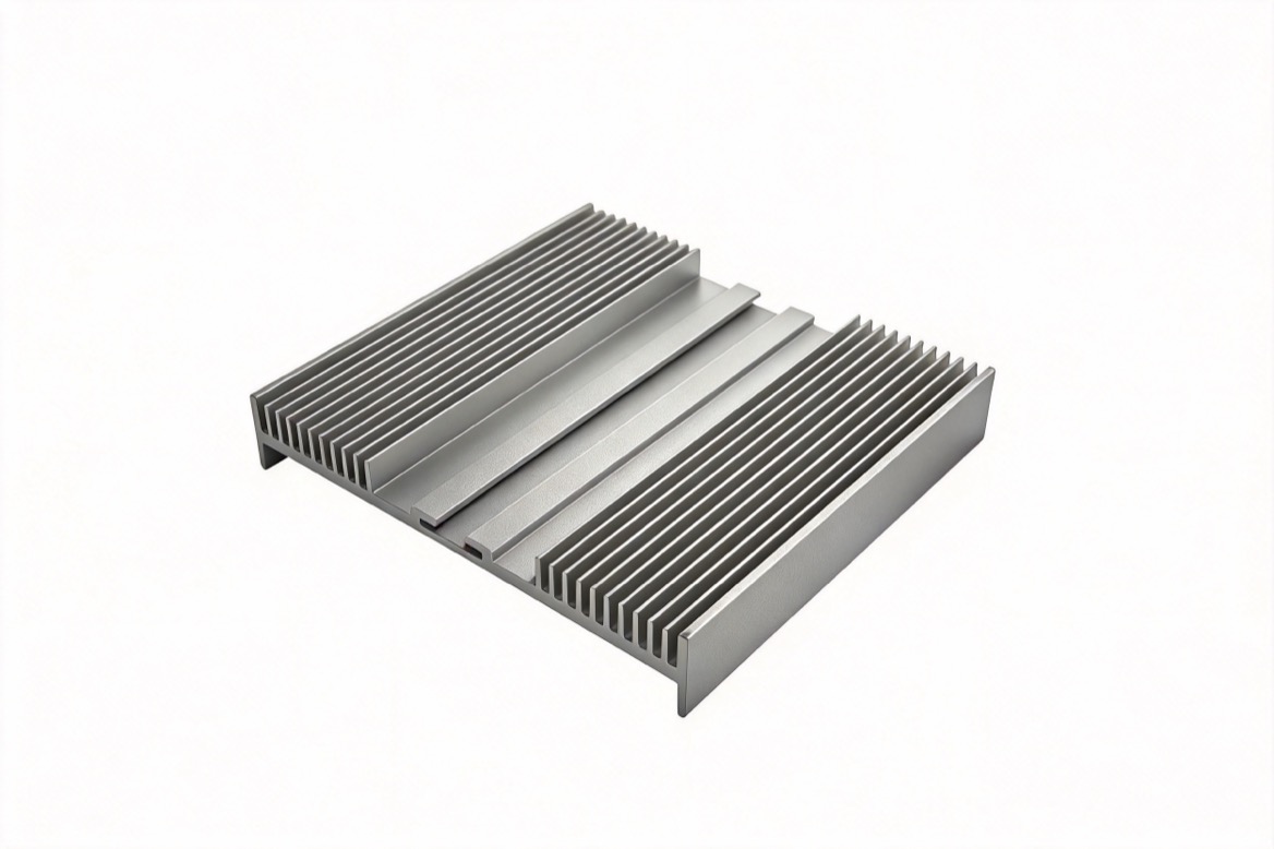
The most expensive mistakes often begin with an incomplete dimension. A buyer requests a "20 mm U-channel," while the designer means a 20 mm internal opening and the supplier quotes a 20 mm external width. Both parties may believe they followed the request.
A useful channel drawing identifies outside width, internal opening, leg height, nominal wall thickness, corner radii, and cut length. Add a section view showing how the mating part enters and where it contacts the aluminum.
Not every surface needs the same degree of control. Mark the features that affect function: a panel groove, a sliding interface, a mounting slot, or a machined datum. Agree on applicable extrusion tolerances for other features instead of placing one unusually tight tolerance across the entire cross-section.
Open-space dimensions deserve particular attention. The distance between two legs can behave differently from a solid metal dimension during extrusion and subsequent handling. If fit is critical, ask how the supplier will measure the opening and whether inspection occurs before or after finishing.
Practical drawing note: State the accepted tolerance standard and revision, then identify any exceptions on the drawing. Do not write "precision tolerance" without naming the dimensions and inspection method.
A coating can change an internal fit. A drilled hole near an edge can reduce the remaining material available to a fastener. A long, slender channel may need inspection for straightness or twist, not just cross-section width.
Review the channel in its final state: cut, finished, and assembled. A sample that fits before anodizing or coating is not necessarily proof that the finished production part will fit. Approve the sample against the same drawing and finish specification that will govern the order.
Many architectural and industrial extrusions use alloys from the 6xxx series. Within that group, 6063 is often considered when a clean surface and complex extruded shape matter. 6061 is commonly considered for applications that place more emphasis on strength or machining. These are starting points, not automatic substitutions for one another.
Temper matters as much as the alloy number. A request for "6063 aluminum" leaves the mechanical condition unspecified. Depending on the design, 6063-T5 and 6063-T6 may have different minimum property requirements. The applicable values can also depend on wall thickness and product specification.
Use the following order when discussing material with an extruder:
1. Describe the function. Is the channel decorative, a guide, a support, or part of a load-carrying assembly?
2. Identify the loads and environment. Include any relevant repeated use, outdoor exposure, or contact with other materials.
3. Select a proposed alloy and temper. Have the design team check the required properties against the applicable product specification.
4. Review fabrication. Confirm whether cutting, machining, forming, or welding occurs after extrusion.
5. Approve the documented material. Put the final alloy, temper, and inspection requirements on the purchase drawing.
Welding deserves special attention. Heat can reduce strength near a weld in heat-treated aluminum. A load-bearing welded channel therefore requires evaluation of the welded assembly, not just the unwelded profile.
A finish affects appearance, handling, and durability. It should be selected early enough to influence groove clearances, visible-surface requirements, and packaging.
- Mill finish: Suitable when the natural extrusion appearance is acceptable or another process will follow. Define allowable cosmetic marks if appearance matters.
- Anodizing: Useful for a metallic appearance and a durable surface. Specify the required appearance range and performance requirements rather than requesting only "clear anodized."
- Powder or liquid coating: Useful when a defined color is required. Specify a coating system appropriate to the intended exposure, including pretreatment and any relevant performance requirement.
For outdoor use, avoid choosing solely by color sample. A finish that works on an interior machine guard may not suit an exposed architectural detail. Where parts will be visible together, approve reference samples and discuss acceptable variation between production batches.
Packaging is part of finish control. If a channel has a visible face or a narrow functional groove, identify both on the drawing. That helps the supplier protect the appearance without leaving packing material or damage in the mating area.
Consider an *illustrative* equipment enclosure with a removable panel guided by two aluminum channels. The initial request says only: "Supply U-channels to fit our panel." That is not enough for a reliable quote.
First, the buyer records the panel's thickness range and the clearance needed for removal. The designer then marks the internal opening and contact faces as critical dimensions. Next, the team checks whether the channel needs mounting holes, a defined surface finish, and access to clean the groove after installation.
The result is a more useful request: a cross-section drawing, proposed alloy and temper, finished cut length, hole locations, finish requirement, required quantity, and inspection points. The supplier can now identify manufacturability concerns before a production die or full order is approved.
The lesson applies equally to machinery guards, architectural trim, and transportation interiors. Specify the interface first. Shape names help start a conversation; fit and function finish it.
Custom extrusions can combine a groove, mounting face, and locating feature in one profile. That can simplify assembly, but the first quote should be based on complete information rather than a sketch alone.
Send the following with an inquiry:
- A dimensioned cross-section and, if available, a 3D model.
- The intended application and whether the part is load-bearing.
- The proposed alloy and temper, or the performance requirements needed to select them.
- Critical mating dimensions and the required tolerance standard.
- Cut lengths, length tolerances, and any machining or holes.
- Finish, visible surfaces, and acceptable appearance range.
- Estimated order quantity, delivery destination, and packaging needs.
- Any sample approval, inspection record, or material documentation required.
Ask the manufacturer to review wall balance, tight corners, long unsupported legs, and difficult-to-finish grooves. A small design adjustment at this stage may improve production consistency without changing the channel's function.
For export orders, clarify whether the quotation covers raw extrusions or fully processed components. Confirm the agreed unit of sale, packing method, and inspection documents. A low profile price is not a low delivered cost if downstream machining, rejects, or damaged finishes are left unresolved.
Guangdong Dapeng Aluminum Industry Co., Ltd. focuses on aluminum-profile development, manufacturing, and export. The company offers industrial and architectural profiles as well as customized downstream processing for applications across construction, industrial manufacturing, transportation, and new-energy equipment.
A useful manufacturer discussion starts with your drawing and operating requirements, not a promise that one catalogued shape suits every project. Share the mating parts, expected production volume, finish, and any critical inspection points. The technical team can then discuss a suitable channel geometry and the processing steps needed to deliver the finished component.
Have a channel drawing or a fit problem to solve? Send Guangdong Dapeng Aluminum Industry Co., Ltd. your cross-section, application details, finish requirements, and target quantity to request a manufacturability review and quotation.
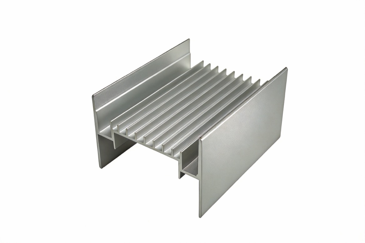
A U-channel generally has two legs extending from a base to form an open groove. A C-channel may have a more enclosing opening or inward-facing lips, but suppliers use these names differently. Compare dimensioned cross-sections instead of ordering by name alone.
There is no universal best alloy. A visible architectural profile may favor the extrusion and surface-finish characteristics of 6063. Another component may call for the properties or machining characteristics associated with 6061. Confirm the alloy and temper against the actual application.
Potentially, but its shape name does not establish its capacity. A qualified designer must consider the cross-section, alloy and temper, span, load direction, connections, and any welding. Obtain project-specific calculations where the channel is part of a load-carrying or safety-critical assembly.
Show the overall cross-section, internal opening, leg heights, wall thicknesses, radii, and cut length. Clearly mark the surfaces and dimensions that mate with another part. Add hole locations, finish, and the applicable tolerance requirements when relevant.
Yes, when fit, appearance, or processing is important. Inspect a sample in its finished condition against the approved drawing, and test it with the mating parts. Record any approved changes before releasing the production order.
Finishing can affect a close-fitting interface, so do not assume a mill-finish sample represents the finished part. Tell the supplier which internal dimensions are critical and confirm how they will be measured after finishing.
Consider a custom profile when a standard channel requires extensive machining, extra brackets, or compromises at the mating interface. Compare the complete component and assembly cost, including tooling, processing, inspection, and expected order volume.
1. Orange Aluminum. ["A Comprehensive Guide to Different Extruded Aluminum Channels."] Original article reviewed for scope and terminology. [orangealuminum]
2. Aluminum Extruders Council. [*Aluminum Extrusion Manual*, 4.2 edition, 2018 update.] Industry guidance on extrusion design, fabrication, finishing, and tolerances. [tricityextrusion]
3. Aluminum Extruders Council. ["Aluminum Extrusion Tolerances."] Guidance on standard and precision tolerances and supplier–designer discussion. [aec]
4. The Aluminum Association. ["Industry Standards."] Background on aluminum alloys, 6xxx-series applications, and the ANSI H35 standards program. [aluminum]
5. Hydro. ["Alloy 6063" product data sheet, revision 2026/01.] Alloy applications, temper definitions, and thickness-dependent property limits. [hydro]
6. ANSI. ["ANSI H35.2-2024: Dimensional Tolerances for Aluminum Mill Products."] Overview of the dimensional-tolerance standard and its revision. [blog.ansi]
7. J. Randolph Kissell, P.E., *STRUCTURE Magazine*. ["The 2020 Aluminum Design Manual."] Structural-design context, connections, and weld-affected strength. [structuremag]
8. SAF. ["How to Decide Between Anodizing, Painting, and Powder Coating."] Practical architectural-finish selection considerations. [saf]


